Rigid Pavement Construction/Cross Section
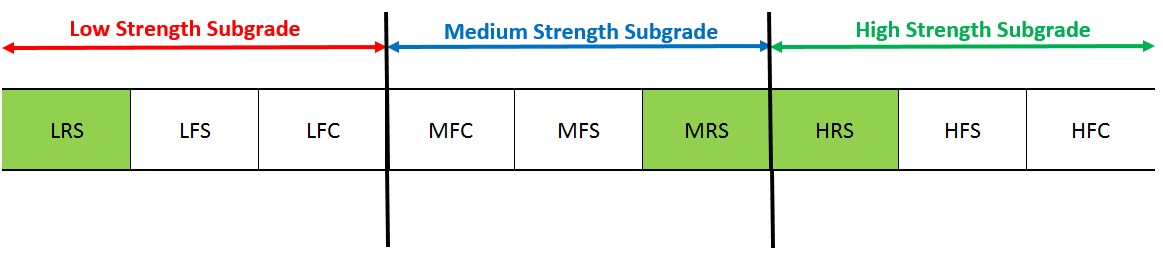
The CC-1 test pavement was built at the same time as the NAPTF. Test item construction was completed in May 1999, shortly after the opening of the facility in April 1999. The CC1 experiment included nine pavement test items; six flexible and three rigid. The nine test items were constructed on three different subgrade strengths characterized as low (target CBR 4); medium (target CBR 8) and high (target CBR 20). The rigid pavement test items were constructed on P-306 Econocrete base. The table below presents the test items designations. Test items designations presented in the table below includes three characters. The first character indicates the subgrade strength: L for low, M for medium, and H for high. The second character indicates the test pavement type: F for flexible and R for rigid. The third character indicates the base type: S for Stabilized, C for Conventional. North and south sides of the test items were subjected to different traffic loading while having similar structures.
CC1 Test Items Designations
|
Test Item Designation
|
Subgrade Type
|
Pavement Type
|
Base
|
|
LFS
|
Low Strength
(Design CBR 4)
|
Flexible
|
P-401 asphalt stabilized
|
|
LFC
|
P-209 crushed stone
|
|
LRS
|
Rigid
|
P-306 Econocrete
|
|
MFS
|
Medium Strength
(Design CBR 8)
|
Flexible
|
P-401 asphalt stabilized
|
|
MFC
|
P-209 crushed stone
|
|
MRS
|
Rigid
|
P-306 Econocrete
|
|
HFS
|
High Strength
(Design CBR 20)
|
Flexible
|
P-401 asphalt stabilized
|
|
HFC
|
P-209 crushed stone
|
|
HRS
|
Rigid
|
P-306 Econocrete
|
Plan View of the NAPTF Test Items during Construction Cycle 1 (Click to Zoom)
A 20 ft. slab pattern was determined based on consideration of data acquisition requirements. This required a minimum width of 60 ft. for a three slab width. Minimum test item lengths of 100 ft. were established for rigid pavements.
To estimate the minimum depth of controlled subgrade construction, both layered elastic theory (LET) and finite element method (FEM) computations were performed to evaluate the influence of the weaker or stronger layers on key response parameters such as subgrade vertical strain, asphalt horizontal strain or concrete tensile stress. The results show that after approximately 3 to 4 ft. depth, an underlying layer will have a small relative effect on a measured test parameter.
Since the maximum pavement thicknesses for rigid sections vary from approximately 21 to 26 inches depending on subgrade strength, the depth of the controlled subgrade vary between items. Below is the cross section of the concrete test sections for Low (test item 1-1), Medium (test item 2-3), and High (test item 3-1) Strength Subgrades. The table below the cross section specifies thickness, depth, and CBR values for each test item, while the drawing itself is shared.
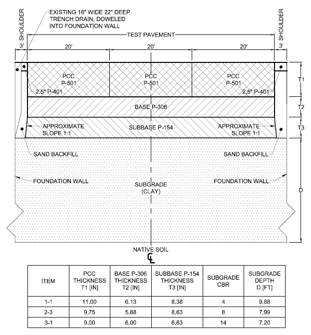
Rigid Pavement Cross Section for all Low, Medium, and High Strength Subgrade (Click to Zoom)
Click here to download the CC1 Historical Drawings with pavement cross sections.
The table below presents the cross sectional details of the CC1 test items. Material properties were according to the FAA advisory circular AC 150/5370-10.
CC1 Pavement Cross-sectional Detail (Gervais et al. 2004)
|
Item ID
|
Surface Layer
|
Base Layer
|
Subbase Layer
|
Subgrade
|
|
Type
|
Thickness (in.)
|
Type
|
Thickness (in.)
|
Type
|
Thickness (in.)
|
Soil Type
|
CBR
|
Strength
|
|
LRS
|
P-501
|
11
|
P-306
|
6
|
P-154
|
8
|
MH-CH
|
4
|
Low
|
|
LFS
|
P-401
|
5
|
P-401
|
5
|
P-209
|
30
|
MH-CH
|
4
|
Low
|
|
LFC
|
P-401
|
5
|
P-209
|
8
|
P-154
|
36
|
MH-CH
|
4
|
Low
|
|
MFC
|
P-401
|
5
|
P-209
|
8
|
P-154
|
12
|
CL-CH
|
8
|
Medium
|
|
MFS
|
P-401
|
5
|
P-401
|
5
|
P-209
|
8.5
|
CL-CH
|
8
|
Medium
|
|
MRS
|
P-501
|
10
|
P-306
|
6
|
P-154
|
9
|
CL-CH
|
8
|
Medium
|
|
HRS
|
P-501
|
9
|
P-306
|
6
|
P-154
|
6
|
SW-SM
|
20
|
High
|
|
HFS
|
P-401
|
5
|
P-401
|
5
|
None
|
-
|
SW-SM
|
20
|
High
|
|
HFC
|
P-401
|
5
|
P-209
|
11
|
None
|
-
|
SW-SM
|
20
|
High
|
Links:
Geometry Design
Pavement Design
Return to Construction Cycle 1 Main Page