Geometry Design
NAPTF Width
In designing the dimensions of CC1 test items, the width of the test track is influenced by factors such as wheel spacing, wander pattern and boundary condition. A typical wheel configuration consists of two tracks, each comprising one to three dual wheel axles in tandem.
An Industry Working Group consisting of pavement experts from the FAA, Boeing Company, U.S. Army, Navy, Air Force, Federal Highway Administration, university professors and engineering consultants, specified the maximum lateral spacing between the center lines of the tracks to be at least 20 ft. (6 m). Also, the required spacing between the extreme outside wheels was estimated to be 26 ft. (8 m) (McQueen 2000). Also, the panel determined a wander width of approximately 60 to 80 inches (50 to 200 cm).
To determine the minimum distance required from the outer wheel of the test gear to the edge of the foundation wall, both layered elastic theory (LET) and finite element method (FEM) analysis were performed on a variety of pavement structures as documented by Hayhoe et al. 1993. Based on the study results, it was decided to keep 10 ft. (3 m) as the minimum distance in addition to the shoulder pavement, planned at 3 ft. (1 m) on each side of the test pavement (McQueen 2000). After consideration of data acquisition requirements, a 20 ft. (6 m) slab pattern was specified by the working Group. This required a minimum width of 60 ft. (18.5m) for a three slab width. With two 3 ft. (1 m) wide shoulders, the total recommended width was set to 66 ft. (20.5 m).
NAPTF Length
Since it was decided to plan the facility with three subgrade strengths, the overall length of the facility was set to the total length of each test item plus a transition area between test items and the length required for run up of the test vehicle and the ramp for construction and support vehicle access. Minimum test item lengths of 60 ft. (18 m) and 100 ft. (30 m) were established for flexible pavements and rigid pavements respectively. The transition length of 25 ft. (8 m) was selected. Therefore, the length of the CC1 experiment added up to 300 ft. (92 m) (McQueen 2000)
Subgrade Depth
To estimate the minimum depth of controlled subgrade construction, both layered elastic theory (LET) and finite element method (FEM) computations were performed to evaluate the influence of the weaker or stronger layers on key response parameters such as subgrade vertical strain, asphalt horizontal strain or concrete tensile stress. The results show that after approximately 3 to 4 ft. (1 to 1.2 m) depth, an underlying layer will have a small relative effect on a measured test parameter (McQueen 2000).
Since the maximum pavement thicknesses vary from approximately 21 to 48 inches (53 mm to 1220 mm) depending on subgrade strength, as shown in the three figures below, the depth of the controlled subgrade vary between items.
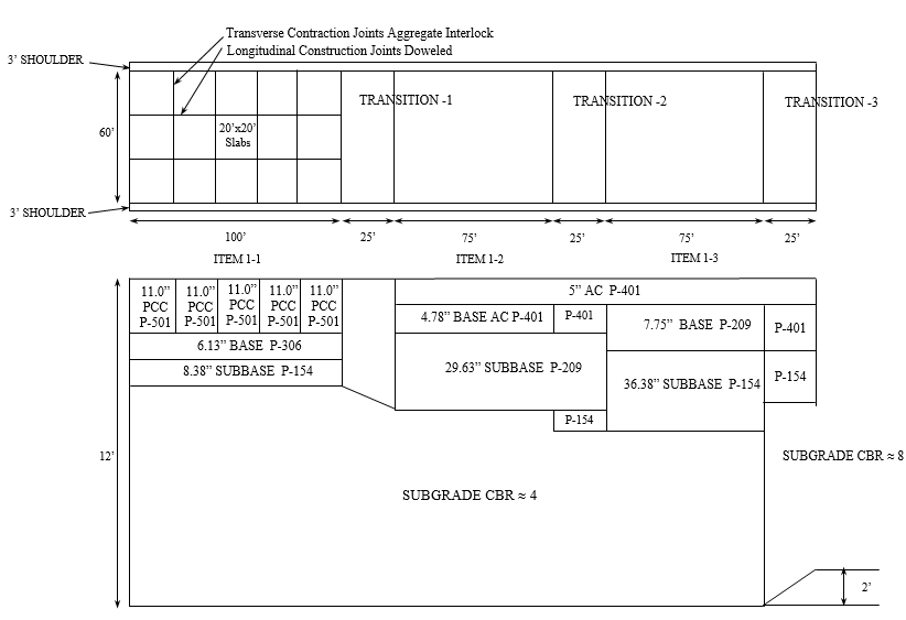
Pavement Cross Section for Items on Low Strength Subgrade (Click to Zoom)
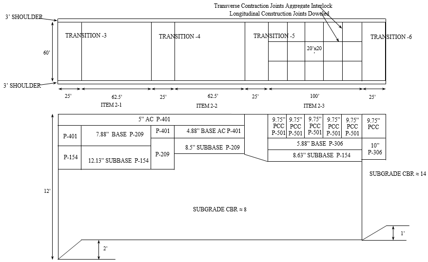
Pavement Cross Section for Items on Medium Strength Subgrade (Click to Zoom)
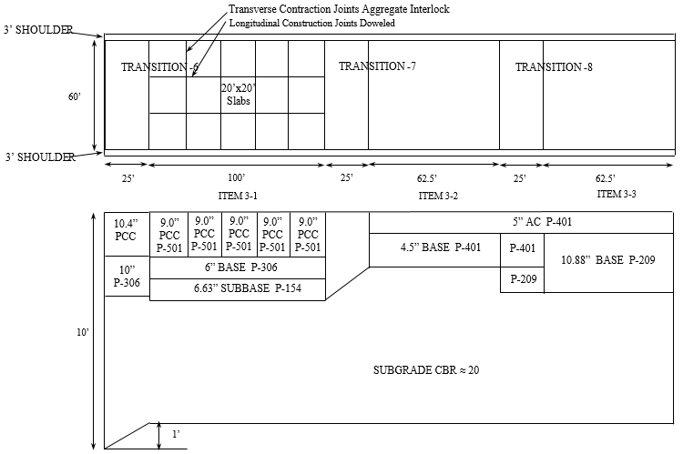
Pavement Cross Section for Items on High Strength Subgrade (Click to Zoom)
Return to Construction Cycle 1 Pavement Cross Section