Response Summary View
Contains information summarizing the results of the Reflective Cracking Phase testing cycles, including Sensor id, sensor name, sensor type, test section id, cycle number, response, response value and response time. Below are the column names and descriptions to query the RC database for Phase VII.
The testing parameters for Phase VII are as follows: Target temperature at overlay bottom 32 ºF,
maximum joint opening 12 mils, (12 x 10-3 in), loading cycle time 150 seconds and rest period 600 seconds.
| dbo.Response6 |
|
SensorID
|
Sequential number used for sensor identification
|
|
SensorName
|
Name assigned to the sensor. The first letters identify the sensor type:
POT = Potentiometer
LVDT = Linear Variable Differential Transducer
JDG = Joint Displacement Gage
EG = Embedded Strain Gage
SG = Surface Strain Gage
T = Thermocouple
NORTH LOAD CELL
SOUTH LOAD CELL
|
|
SensorType
|
Displacement mils(inches x 10-3), Microstrain (strain x 10-6), Temperature (ºF)
|
|
TestSectionID
|
Unique number assigned to identify each of the two test sections.
1= North and 2 = South
|
|
CycleNum
|
The number of the cycle.
|
|
ResponseType
(sensor response)
|
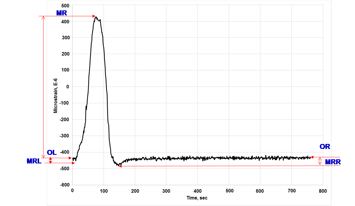
OL = offset left (first reading)
MRL = Minimum Response Left
MR = Maximum Response
MRR = Minimum Response Right
OR = Offset Right
|
|
ResponseValue
|
The value associated with the response.
|
|
ResponseTime
|
The time associated with the response.
|
|
TestParameterID
|
Unique id associated with the specific testing parameters for the corresponding phase
|
Sample Strain Gage Response
