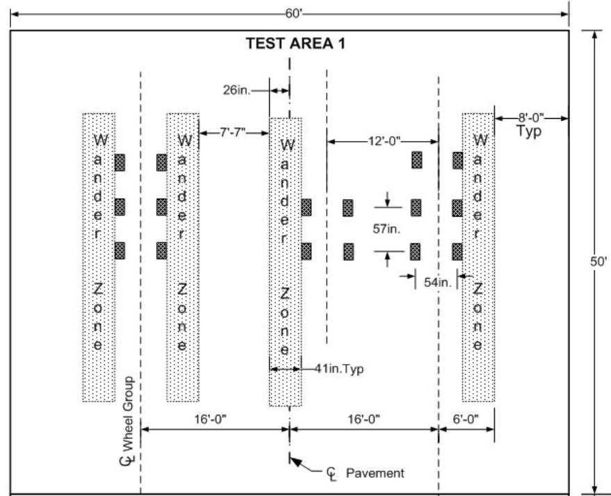
A. Gear Configuration
Below is the gear configuration for test items.
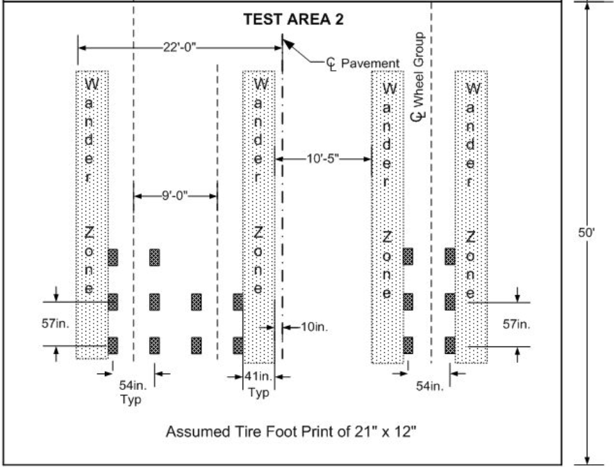
Two landing gear configurations were used for trafficking the test items; a 6-wheel landing gear and a 10-wheel landing gear. Figure below presents Test Area 1. A pavement centerline that divides the test items into north and south sections is shown. The Figure presents the wheels configurations of sections loaded with 10- and 6-wheel gears on different sides. The Figure also depicts wander zones for each group of wheels. The wander zone of the 10-wheel gear extends on both sides of the centerline in Test Area 1 configuration. In Test Area 2 configuration, however, the 10-wheel gear is contained on one side of the pavement centerline and wander zone stops 10 inches from the centerline as shown.
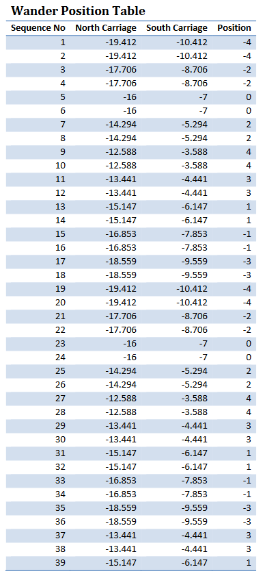
C. Wander Pattern
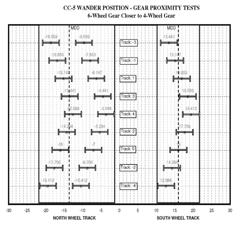
Figure XX Wander Pattern of Sample Sections Loaded with 10-Wheel Gear on North and 6-Wheel Gear on South.
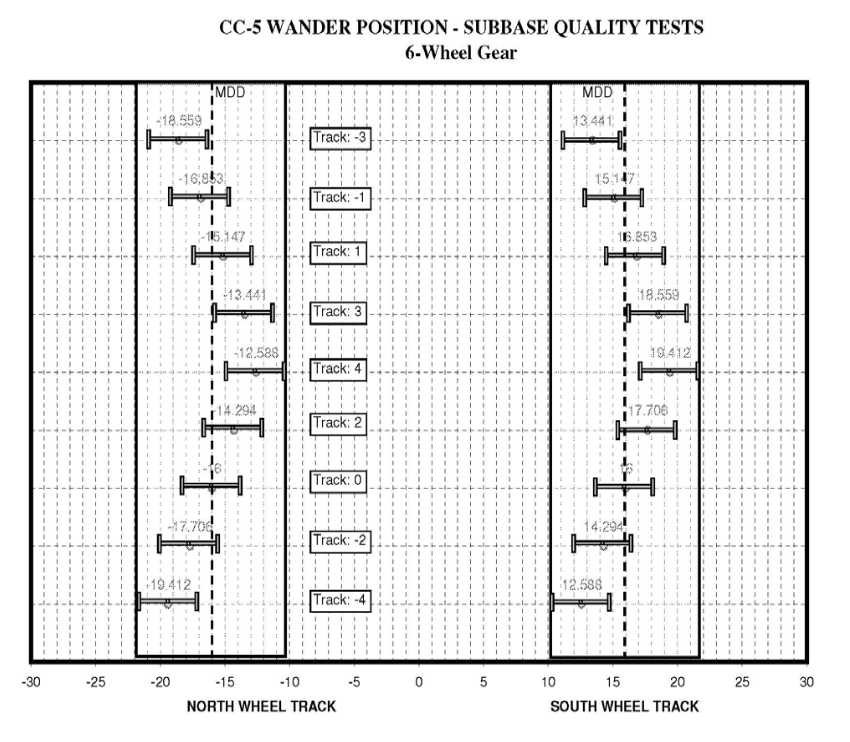
Figure XX. Wander Pattern of Sample Sections Loaded with 6-Wheel Gears on Both Sides.